線段?這主題有點怪?無論是畫 Turtle Spiral Generator,或者是 Symmetrical triangle generator,都需要線段:
可惜的是,OpenSCAD 的內建模組中,並沒有 polyline 這樣的模組,怎麼辦呢?
polygon
在 OpenSCAD 中有個 polygon
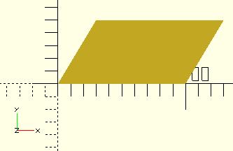
模組,可以用來建立多邊型,最簡單的使用方式就如同官方文件上寫的,只要給定每個頂點,就會自動建立多邊型,也可以指定路徑索引順序,以下幾個都會建立相同的多邊型:
polygon(points=[[0,0],[100,0],[130,50],[30,50]]);
polygon([[0,0],[100,0],[130,50],[30,50]], paths=[[0,1,2,3]]);
polygon([[0,0],[100,0],[130,50],[30,50]],[[3,2,1,0]]);
polygon([[0,0],[100,0],[130,50],[30,50]],[[1,0,3,2]]);
建立出來的圖片,就直接取自官方圖片吧!

兩點決定一線
為什麼突然冒出 polygon
的介紹?這是用來建立多邊型的,不是用來建立直線的模組!好吧!就將話題先拉回,如果想要有個 polyline
模組,可用來指定線段的各個點,然後自動連成一條線,第一個要解決的是什麼呢?
寫程式就是要大任務分解為小任務,因此至少要先能夠兩點決定一個線,第一個想法是,OpenSCAD 有 square
模組,如果寬度設得細細的,就像是條線了,接著可以看看兩點之間的距離決定長度,然後算出與 x 軸的夾角,使用 rotate
旋轉,最後將建立的細長方形移至正確的位置…
想到這邊,就覺得這個方法有點麻煩了,因此第二個想法就是,既然 OpenSCAD 有個 polygon
模組,只要指定頂點就可以畫多邊形,那麼能不能只指定兩個點,另兩個點根據線的寬度來計算,就可以畫出一條直線了?根據這個想法,暫且實作出以下的程式:
module line(p1, p2, width) {
    polygon([
        p1, p2, [p2[0], p2[1] - width], [p1[0], p1[1] - width]
    ]);
}

line([1, 2], [-5, -4], 1);
實作出來的效果還不錯:
這邊只是簡單地將兩個點的 y 座標下移一個線寬,然而,如果你龜毛一點,馬上就會想到,這不是我們要的線寬,線寬應該是上下兩個平行線之間的距離,而不是垂直方向的距離。
既然要龜毛,就龜毛個徹底一些好了,我們想要有這樣的效果:
也就是,畫出來線佔的寬度,會是在兩點之間各佔一半,而根據上圖列出的關係,可以使用三角函式反推 angle:
angle = atan((p2[1] - p1[1]) / (p2[0] - p1[0]));
因此,polygon 模組需要的四個點就是:
offset_x = 0.5 * width * cos(90 - angle);
offset_y = 0.5 * width * sin(90 - angle);
offset1 = [-offset_x, offset_y];
offset2 = [offset_x, -offset_y];
points=[
    point1 + offset1, point2 + offset1,
    point2 + offset2, point1 + offset2
];
將上面的公式整理一下,實作為 line 模組的話:
module line(point1, point2, width = 1) {
    angle = 90 - atan((point2[1] - point1[1]) / (point2[0] - point1[0]));
    offset_x = 0.5 * width * cos(angle);
    offset_y = 0.5 * width * sin(angle);

    offset1 = [-offset_x, offset_y];
    offset2 = [offset_x, -offset_y];

    polygon(points=[
        point1 + offset1, point2 + offset1,
        point2 + offset2, point1 + offset2
    ]);
}

line([1, 2], [-5, -4], 1);
出來的效果如下:
polyline
有了 line 模組可以兩點間畫一條線,接下來就可以實作 polyline
模組了,只要兩個點為一組,將全部的點消耗完就可以了:
module line(point1, point2, width = 1) {
    angle = 90 - atan((point2[1] - point1[1]) / (point2[0] - point1[0]));
    offset_x = 0.5 * width * cos(angle);
    offset_y = 0.5 * width * sin(angle);

    offset1 = [-offset_x, offset_y];
    offset2 = [offset_x, -offset_y];

    polygon(points=[
        point1 + offset1, point2 + offset1,
        point2 + offset2, point1 + offset2
    ]);
}

module polyline(points, width = 1) {
    module polyline_inner(points, index) {
        if(index < len(points)) {
            line(points[index - 1], points[index], width);
            polyline_inner(points, index + 1);
        }
    }

    polyline_inner(points, 1);
}

polyline([[1, 2], [-5, -4], [-5, 3], [5, 5]], 1);
畫出來的效果是:
咦?怎麼缺角了?因為基本上,line
模組實作出來是個長方形嘛!解決缺角的一個方式是,在兩點構成的線兩端加上個小圓:
module line(point1, point2, width = 1, cap_round = true) {
    angle = 90 - atan((point2[1] - point1[1]) / (point2[0] - point1[0]));
    offset_x = 0.5 * width * cos(angle);
    offset_y = 0.5 * width * sin(angle);

    offset1 = [-offset_x, offset_y];
    offset2 = [offset_x, -offset_y];

    if(cap_round) {
        translate(point1) circle(d = width, $fn = 24);
        translate(point2) circle(d = width, $fn = 24);
    }

    polygon(points=[
        point1 + offset1, point2 + offset1,
        point2 + offset2, point1 + offset2
    ]);
}

module polyline(points, width = 1) {
    module polyline_inner(points, index) {
        if(index < len(points)) {
            line(points[index - 1], points[index], width);
            polyline_inner(points, index + 1);
        }
    }

    polyline_inner(points, 1);
}

polyline([[1, 2], [-5, -4], [-5, 3], [5, 5]], 1);
完成的效果如下:
效果感覺還不錯呢!實際上,這只是畫線一種實現方式,根據需求的不同,還可以有其他的實作方式,舉個例子來說,Archimedean spiral generator 就使用了另外一種線段的實作方式,這可以改天再來談,你也可以試著動腦想想看,這也是使用程式建模的樂趣之一喔!


